Instruction Execution
The execution of a program on the computer proceeds in three distinct phases: fetch, decode, and execute. These three steps are repeated for every instruction, and they continue until either the computer executes a HALT instruction or there is a fatal error that prevents it from continuing (such as an illegal op code, a nonexistent memory address, or division by zero). Algorithmically, the process can be described as follows:
While we do not have a HALT instruction or a fatal error
Fetch phase
Decode phase
Execute phase
End of the loop
This repetition of the fetch/decode/execute phase is called the Von Neumann cycle. To describe the behavior of our computer during each of these three phases, we will use the following notational conventions:
CON(A) The contents of memory cell A. We assume that an instruction occupies 1 cell.
A—>B Send the value stored in register A to register B.
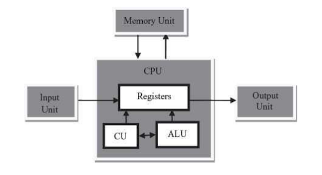
The following abbreviations refer to the special registers and functional units of the Von Neumann architecture introduced in this chapter:
PC The program counter
MAR The memory address register
MDR The memory data register
R The instruction register, which is further divided into Rop, and Raddr .
ALU The arithmetic/logic unit
R Any ALU registe
GT,EQ, LT The condition codes of the ALU
+1 A special increment unit attached to the PC
FETCH Initiate a memory fetch operation (that is, send an F signal on the F/S control line
STORE Initiate a memory store operation (that is, send an S signal on the F/S control line
ADD Instruct the ALU to select the output of the adder circuit (that is, place the code for ADD
on the ALU selector lines.
SUBTRACT Instruct the ALU to select the output of the subtract circuit (that is, place the code for SUBTRACT on the ALU selector lines
Fetch Phase
During the fetch phase, the control unit gets the next instruction from memory and moves it into the IR. The fetch phase is the same for every instruction and consists of the following four steps.
1.PC—> MAR Send the address in the PC to the MAR register.
2. FETCH Initiate a fetch operation using the address in the MAR. The contents of that cell are placed in the MDR.
3. MDR—>IR Move the instruction in the MDR to the instruction register so that we are ready to decode it during the next phase.
4, PC+1—>PC Send the contents of the PC to the incrementor and put it back. This points the PC to the next instruction.
The control unit now has the current instruction in the IR and has updated the program counter so that it will correctly fetch the next instruction when the execution of this instruction is completed.
Decoding Phase
Decoding the instruction is simple because all that needs to be done is to send the op code portion of the IR to the instruction decoder, which determines its type.
IRop —> instruction decoder
The instruction decoder generates the proper control signals to activate the circuitry to carry out the instruction.
Execution Phase
The specific actions that occur during the execution phase are different for each instruction. Therefore, there will be a unique set of circuitry for each of the 2^k distinct instructions in the instruction set. The control unit circuitry generates the necessary sequence of control signals and data transfer signals to the other units (ALU, memory, and I/O) to carry out the intent of this instruction. The following examples show what signals and transfers take place during the execution phase of some of the instructions in using the Von Neumann model of computer
a) LOAD X Meaning: Load register R with the current contents of memory cell X.
1. IRaddr —>MAR Send address X (currently in IRaddr ) to the MAR.
2. FETCH Fetch contents of cell X and place that value in the MDR.
3.MDR—>R Copy the contents of the MDR into register R.
b) STORE X Meaning: Store the current contents of register R into memory cell X.
1.IRaddr —> MAR Send address X (currently in IRaddr) to the MAR.
2. R —>MDR Send the contents of register R to the MDR.
3. STORE Store the value in the MDR into memory cell X.
c) ADD X Meaning: Add the contents of cell X to the contents of register R and put the result back into register R.
1.IRaddr —>MAR Send address X (currently in IRaddr ) to the MAR.
2. FETCH Fetch the contents of cell X and place it in the MDR.
3. MDR —> ALU Send the two operands of the ADD to the ALU.
4.R—> ALU
5. ADD Activate the ALU and select the output of the ADD circuit as the desired result.
6. ALU —> R Copy the selected result into the R register.
Comments
Post a Comment