Local Area Networks - LAN
A local area network (LAN) is a network that connects computers and other supporting devices over a relatively small localized area, typically a room, the floor of a building, a building, or multiple buildings within close range of each other. Usually, most of the computers in a local area network are personal computers or workstations, although sometimes there may be larger server computers present. Supporting devices might include printers, external storage devices, and routers. Routers, and perhaps gateways, will be used to connect the LAN to other networks.
Some LANs are further limited in geographical scope by the particular medium in use. Wireless Ethernet, commonly identified by its trade name, Wi-Fi, for example, is limited to a maximum range of a few hundred feet under ideal conditions by the usable strength of the radio signal that is used to carry the data. Walls and other obstructions will limit the range of the signal even more.
Since all communication channels are limited in the amount of data that they can carry, it is sometimes useful to design a LAN to minimize extraneous traffic on the network where possible. One common way to do this in business is to create separate LANs for different business functions or departments. Traffic between the different LANs is enabled by connecting the LANs together with a backbone network, as described later in this section. For example, there would be a LAN for the accounting department, a LAN for the marketing department, and so on. The interconnection between networks allows the different departments to communicate with each other, as well as to access data stored on central company servers.
There are different kinds of local area networks, each defined by its network protocols, particularly the data link and physical layers, maximum bit rate, connecting media, topology (the physical and logical layout), and various features. Most modern local area networks are based on a set of standards and associated protocols called Ethernet. They are also identified by their IEEE standards.The standards define Ethernet at the data link and physical layers. Although Ethernet comes in a number of ‘‘flavors’’, three are prevalent: switched Ethernet (IEEE 802.3), Wi-Fi (IEEE 802.11), and hub-based Ethernet (also IEEE 802.3). The Ethernet protocols are designed to make It is possible to mix different flavors in a single network. There are a number of variations on each flavor. Figure 12.21 describes the features of some of the prevalent Ethernet standards.
As an example of how Ethernet units operate together, consider a home network with a router that also provides a wireless access point and an Ethernet switch. The router uses Ethernet to connect to a DSL or cable modem for Internet access, an Ethernet cable connects a printer directly to the switch, and one or more computers use wireless Ethernet to connect wirelessly. See Figure 12.22.
A hub-based Ethernet is shown in Figure 12.23. A hub is a passive central connection device used to simplify wiring and maintenance. A hub is a layer 1 physical layer device. All of the connections at the hub are simply tied together inside the hub. The word ‘‘passive’’ means that the hub performs no oper- ation or modification of the signals as they arrive at the hub. Signals arriving at the hub are simply broadcast in their original form to every other device connected to the hub. The signals, of course, represent frames. Since each frame has a destination address, the NICs simply ignore the broadcast data for any frame whose destination address does not match that of the NIC.
Because every device connected to the hub is sharing the bandwidth of the network, the bandwidth available to individual connections decreases at least proportionally to the number of units using the network. When traffic is heavy, there may be many devices contending for use of the bus. A medium access control protocol called CSMA/CD (Carrier Sense Multiple Access with Collision Detection) is used to manage access to the bus.
Hubs are used primarily in local area networks, but are also sometimes seen in backbone networks. However, the use of hubs is declining because better performance can be obtained from other devices that can isolate and operate on individual nodes, particularly switches.
Figure 12.24 shows an alternative topology called switched Ethernet. Switched Ethernet is based logically on a star topology. Each node of the network is connected to a central switch that is capable of connecting any two nodes together. When a node on the network wishes to communicate with another node, the switch sets up a direct connection between the two. Standard Ethernet cables contain at least two pairs of wires, which are used to make the connections full-duplex. Multiple pairs of nodes can communicate at full bandwidth through the switch simultaneously. For wired local area networks, switched Ethernet is the prevalent method in use today.
Wireless Ethernet, or ‘‘Wi-Fi’’ is a radio-based, compatible extension to the Ethernet standard. Wi-Fi is based around a central access point that is somewhat equivalent to a hub. However the access point is an active node, since it must transmit and receive radio waves to communicate with the nodes.
There are a number of different ver- sions of the Wi-Fi standard, operating at different radio frequencies and with different bit rates. Only those operating at the same radio frequency are compatible with each other, however Wi-Fi components that operate at higher bit rates can slow their data rate for compatibility with slower speed units. Some access points and NICs support multiple radio frequencies. Figure 12.25 compares the features of the current Wi-Fi standards.
Nodes on a Wi-Fi LAN attempting to transmit simultaneously are more difficult to manage with Wi-Fi than with hub-based Ethernet, particularly because it is possible for units to have radio signals that are strong enough to communicate with the access point but still be far enough apart to be unaware of each other’s presence. The Wi-Fi standard provides a number of medium access protocols to handle possible interference between nodes. These protocols are proactive. They are designed to avoid collisions, unlike the hub protocol, which is designed simply to detect and correct for collisions.
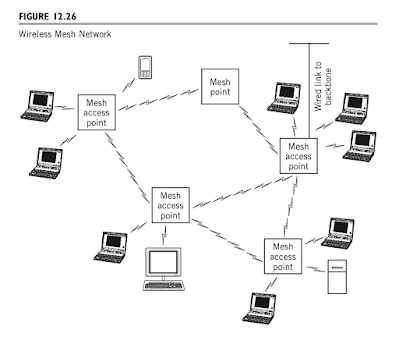
Traditionally, multiple access points have been linked by wire. A new standard introduces the concept of mesh points, which extends the range of a wireless network by creating a wireless mesh network of access points. Mesh points operate at the medium-access control layer (layer 2) and are essentially invisible to the upper layers of the network. This new standard effectively adds backbone capability to wireless networking. Figure 12.26 shows a simple wireless mesh network.
Backbone Networks
Backbone networks are used to interconnect local area networks. A backbone can tie several local area networks together to provide for the passage of data between the individual networks and from the networks to the Internet or other external network resources. A primary motivation for a backbone network is to improve overall performance of a larger network by creating separate local area networks for groups of users who communicate primarily with each other. Network traffic can be isolated into small areas of usage, replacing one large heavily used local area network with a number of smaller, isolated LANs. The backbone enables communication between the individual LANs when it is required. For example, a college campus might have LANs built around dormitory areas, plus wireless access points in classrooms, study areas, libraries, dining halls, and various other points around the campus where people congregate. A backbone network would provide the interconnections between all of these LANs. The backbone network also makes it possible to extend the overall range of the combined networks well beyond that of a single LAN. In this case fiber optic cables in the backbone combined with the use of switches makes coverage of a large geographical area, such as a large college campus, feasible.Some network designers actually call this backbone network layout tiered Ethernet.
There are two additional features to observe in the backbone network shown in Figure 12.27. First, is the presence of a server. Since it is located directly on an arm of the backbone it is readily available from every LAN. The other feature is a router or gateway that will connect the backbone to other networks through a common carrier. This feature will enable the capabilities of metropolitan and wide area networking.
Backbone networks are well suited for small intranets. An intranet is an organizational network where the user interfaces and applications are based primarily on Web services. Its use is restricted to authorized users within the organization. Some network practitioners refer to it as a ‘‘private Internet’’. Intranets for larger organizations require the connectivity of metropolitan area networks or wide area networks. As we discuss next, the primary limiting factor in larger networks is the ability to connect separate locations over intervening public and private property.
It is worth mentioning that it is possible to design a backbone area network with switches in such a way that the network can be reconfigured dynamically. Specifically, individual hosts can be moved from one local area network to another by changing the settings in the switches. This feature allows the network administrator to tailor the traffic load on various parts of the network to optimize performance. Such a network is called a virtual local area network.


Comments
Post a Comment